
Microlens array is also called fly-eye lens and fly-eye lens. It is an important and basic component of the optical system. Generally, there are a series of tiny unit lenses in a certain arrangement. Different arrangements can result in different imaging results. Generally, the period size of the sub-unit is about tens of um to thousands of um, and the shape of the unit is round, square, free-form surface, hexagon, square, and other shapes.
According to the optical design principle of microlens, we can say that the microlens array is divided into diffractive type and refraction type:
Refractive microlens
Refractive microlens: based on the traditional geometric optics refraction principle, it has the advantages of lighter, smaller, and highly integrated. Its applications mainly include imaging and beam conversion, optical communication, medical treatment, medical aesthetics, and over-beam scanning. Common lens diameters are square, rectangular, hexagonal, and circular.
Diffractive microlens array
Diffractive microlens array: Use surface relief structure modulation to change the wave phase of incident light to achieve the target function. The main problem to be solved is the correction of high-order aberrations, the modulation of the spot shape of any light distribution, optical communication, and various fields such as medical beauty.
The application and distribution of microlens arrays are based on the different arrangements of refractive microlenses, which can be applied to various optical applications. They are mainly divided into full-bodied, M*N-distributed, single-row, and single-row Format arrangement, the following mainly introduces the characteristics of different arrangements and the main application scenarios of different arrangements.
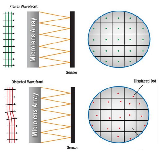
An important application of microlens array Hartmann sensor (Hartmann-Shack)
The Shaker-Hartmann sensor is a wavefront sensor. This wavefront analyzer is an integral part of the adaptive optics system. It can detect the change and distortion of the light wavefront. It uses a microlens array to split the input light wavefront into a beam array. After splitting, each beam is focused on the CCD sensor. As shown in the figure below, each microlens unit will form a focused spot, which can be analyzed by the distribution of the focused spot. Wavefront distortion.
Wavefront distortion will cause the focus of the spot to shift on the optical axis, so the imaging will change from a regular spot to a mixed and lack-solid spot pattern. This information uses optical knowledge to calculate the shape of the wavefront incident on the microlens array. Therefore, this sensor can be used for the characterization of the performance of the optical system, real-time monitoring, and used to control the wavefront distortion before the imaging of the adaptive optical element.
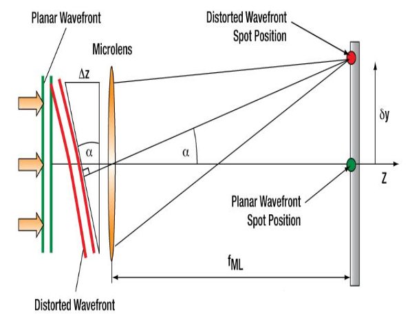
As shown in the figure below, in the microlens of each unit, if the incident light is incident parallel to the lens without distortion, it can be known from geometric optics that the light falls on the focal plane of the optical axis. When the incident light occurs in the microlens unit area Distortion (not parallel to the lens), the position of the spot will be offset in the X and Y directions of the focal plane (shown by the red dot), so each spot will deviate from the optical axis Z of its corresponding microlens at an angle θ. And the angle θ is the same as the angle between the plane wavefront and the lens and the angle between the distortion wavefront and the z-axis.
